
What Is the Full Breakdown of Welding Technology for Thin Gr5 Titanium Foil?
- Gr5 Titanium Foil
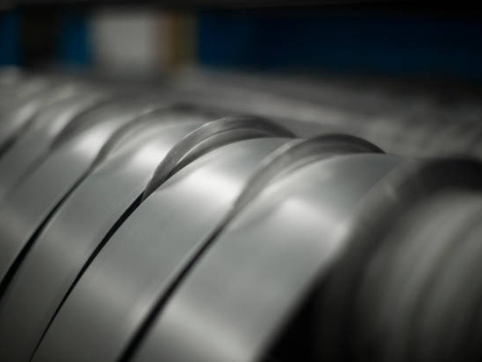
Thin Gr5 titanium foil (Ti-6Al-4V) delivers outstanding strength-to-weight ratio and corrosion resistance. It sees wide use in aerospace, medical devices and new energy industries. Its ultra-thin gauge (0.02 -1.0 mm) and dual alpha-beta microstructure create big welding challenges and narrow working windows. Three reliable welding methods work for this material: TIG welding, laser welding and electron beam welding. All three tools deliver precise heat control under inert gas shielding and stop oxidation and workpiece distortion. Four key steps create sound welds: pick the right welding process, strictly limit heat input (40 ~ 150 J/mm, adjust values for each method), keep back shielding gas purity above 99.99%, and lock workpieces with dedicated fixtures.
1 Why Does Welding Thin Gr5 Titanium Foil Bring Major Difficulties?
1.1 Physical and chemical traits of the material create barriers
Gr5 titanium foil (Ti-6Al-4V) melts at 1668 ℃. It conducts heat poorly, only one fifth the thermal conductivity of steel. Heat gathers inside weld seams and heat affected zones during welding. Local overheating develops from trapped heat. This issue triggers coarse grain growth and hardening, and cuts mechanical performance of welded joints.
Titanium reacts easily with oxygen, nitrogen and hydrogen. Once temperature rises past 400 ℃, titanium soaks up oxygen and nitrogen from air. The reaction builds a hard, low-ductility brittle surface layer called alpha case. Tiny cracks start from this layer. Joint fatigue resistance and crack resistance drop sharply, weld hardness climbs above HV 450, and stretch ability falls fast. Even oxygen pollution above 0.3% makes welds brittle and generates cracks during later forming or service.
The dual alpha-beta titanium alloy goes through clear structural shifts under welding thermal cycles. Its beta phase transition temperature sits between 995 ℃ and 1010 ℃. Cooling speed directly shapes the final metal structure. Fast cooling above the beta transition temperature creates needle-shaped martensite alpha prime grains. Hardness rises and toughness drops. Slow cooling forms thick sheet alpha grains that split the metal base and weaken fatigue performance. Welders must set suitable cooling speeds to balance strength and toughness.
1.2 Ultra-thin gauges set strict limits for welding parameters
Gr5 titanium foil only ranges 0.02 -1.0 mm thick. It carries an extremely narrow safe heat input window for welding. Too much heat burns holes and causes heavy distortion. Too little heat fails full metal fusion and leaves incomplete penetration or trapped impurities.
Ultra-thin foil holds low rigidity. Thermal stress from uneven heating and shrinkage stress during solidification stack together. Combined stress often hits or passes the material’s yield strength. Waves and wrinkles form on foil surfaces. Flatness and assembly accuracy drop, and post-weld flatness correction becomes hard.
Thin foil has a large surface area against its volume. More surface touches air during welding. Weld front side, back side and heat affected zones need full coverage of shielding gas even with argon protection. Missing full shielding leads to oxidized discoloration. Gold, blue or black oxide layers build up and cut joint strength heavily.
1.3 Performance standards and industry rules for welded joints
Aerospace and medical device industries enforce tight standards for Gr5 titanium foil welds. Weld tensile strength must reach at least 90% of base metal strength (≥805.5 MPa), elongation stays above 8%, and fatigue performance passes long cyclic load tests. These rules demand steady, repeatable welding processes.
Core industry standards include ASTM B265, AMS 4911 and AWS D17.1. Weld surfaces cannot hold cracks, air holes or trapped slag. X-ray flaw detection must reach Class II or higher. Controllable hardness gradients inside heat affected zones stop stress concentration points from growing fatigue cracks.
Material Property Comparison Table
| Material Property | Pure Titanium (Gr2) | Gr5 Titanium Alloy (Ti-6Al-4V) |
|---|---|---|
| Tensile Strength | ≥ 340 MPa | 895 ~ 930 MPa |
| Melting Point | 1668 ℃ | 1668 ℃ |
| Welding Sensitivity | Medium | High (prone to oxidation and hardening) |
| Hardening in Heat Affected Zone | Minor | Obvious (hardness rises 50 ~ 100 HV) |
| Recommended Welding Methods | TIG, laser, resistance welding | TIG, laser, electron beam welding |
2 Three Core Welding Technologies for Thin Gr5 Titanium Foil
2.1 TIG Welding – The Most Versatile Precision Welding Tool
Gas tungsten arc welding (TIG) stands as the most common choice for thin Gr5 titanium foil. It generates electric arcs with non-melting tungsten electrodes and runs welding under argon shielding. Operators gain precise heat control and clean weld shaping. TIG welding carries its biggest strengths in simple equipment and low overall cost. It fits small batch production and research trials perfectly.
Welders must lock welding current between 5 A and 40 A. High current burns foil holes, low current fails to build stable molten pools. Welding speed ranges from 3 cm/min to 8 cm/min to secure full fusion depth and even heat input. Pick tungsten electrodes with 1.0 mm to 2.4 mm diameter. Cerium tungsten or lanthanum tungsten electrodes with 30° to 60° tip angles boost arc stability and smooth arc starting.
Use high-purity argon (≥99.99%) for front-side shielding, set gas flow rate 8 ~ 12 L/min. Back-side shielding carries equal importance. Install dedicated trailing shields or sealed slots to cut oxygen content below 50 ppm on weld backsides. Extend shielding gas flow for 15 to 30 seconds after welding. This step protects hot zones from oxidation during cooling.
Prioritize butt joints for welding design. Overlapped joints stack material thickness and raise burn-through risks. Thin Gr5 foil (0.02 -1.0 mm) uses flat I-groove butt joints with assembly gaps 0 ~ 0.1 mm. Material thicker than 1.0 mm adopts 60° to 70° V-grooves with gaps held between 0 and 0.1 mm. Skip filler wire for foil thinner than 0.2 mm. Add ER Ti-5 (Ti-6Al-4V) filler wire (0.8 ~ 1.2 mm diameter) for foil 0.3 mm or thicker.
2.2 Laser Welding – The Top Pick for High-Speed Precision Production
Laser welding uses high energy density laser beams as heat sources. Metal melts and solidifies quickly during operation. Welding speed hits 30 ~ 100 cm/min, far faster than TIG welding. Laser welding creates narrow heat affected zones (normally less than 1 mm) and light workpiece distortion. It works best for ultra-thin foil and automated mass production lines.
Laser welding demands tight focusing accuracy. Focus spot diameter sits 0.1 ~ 0.5 mm. Small adjustments to defocus value change penetration depth and weld shape clearly. Positive defocus (focus point above workpiece) suits thin foil welding. It creates even weld width and avoids burn-through. Negative defocus (focus point inside metal) delivers deep penetration and concentrated heat. Only use this mode for local deep melting and avoid it for ultra-thin foil.
Laser welding also requires inert gas shielding. Fast heat input allows lower shielding gas flow rates (5 ~ 8 L/min). Adopt side-blow shielding design. Gas flows along the welding direction and stops air from mixing into molten pools. Vacuum environments or helium shielding serve high-end applications and cut oxidation risks further.
Pore control creates the main challenge for laser welding. Ultra-fast cooling traps dissolved hydrogen, nitrogen and other gases inside molten pools before they escape. Tiny air holes form inside weld seams. Four practical fixes solve this issue: heat base material to 50 ~ 100 ℃ and slow cooling speed; turn on pulse laser mode and leave time for gas release; fully clean weld surfaces and wipe away oil and moisture; adjust laser power and speed to avoid overly deep molten pools.
2.3 Electron Beam Welding – The Leader for Extreme Precision and Deep Penetration
Electron beam welding (EBW) runs inside vacuum chambers with pressure 10⁻² ~ 10⁻⁴ Pa. High-speed electron beams hit workpiece surfaces and generate welding heat. The vacuum environment fully blocks oxygen and nitrogen contamination, making it ideal for high-purity titanium alloy welding. Electron beams carry ultra-high energy density (10⁶ ~ 10⁸ W/cm²). Operators achieve stable welding even for 0.02 mm ultra-thin foil.
Electron beam welding targets high-end sectors such as aerospace and medical devices. Welds hold high purity, uniform microstructure and premium mechanical performance. Weld tensile strength reaches over 95% of base metal strength with great fatigue resistance. Heat affected zones stay narrower than 0.5 mm, and workpiece distortion only hits one third to one half of distortion from TIG welding.
Two major limits slow its wider use: extremely high equipment investment (single machine costs millions of US dollars), and workpiece size limits set by vacuum chamber dimensions. It cannot handle oversized workpieces or on-site welding tasks. Workers must fully clean workpiece surfaces before welding and strip all oxide layers and oil. Dirty surfaces drop electron beam energy transfer efficiency.
Set acceleration voltage between 30 kV and 60 kV, control beam current from 5 mA to 50 mA. Welding speed reaches 50 ~ 150 cm/min, much higher than TIG welding. Fine tuning focus current adjusts focus point position and spot diameter (0.1 ~ 0.3 mm). Operators shift freely between surface welding and deep penetration welding modes.
Full Comparison of Three Welding Methods
| Welding Method | Heat Input Control | Welding Speed | Applicable Thickness | Equipment Cost | Shielding Solution |
|---|---|---|---|---|---|
| TIG Welding | Medium (needs precise fine-tuning) | 3 ~ 8 cm/min | 0.05 ~ 0.8 mm | Low | Argon shielding |
| Laser Welding | High (ultra-fast heating) | 30 ~ 100 cm/min | 0.02 -1.0 mm | Medium to High | Argon / Helium shielding |
| Electron Beam Welding | Extremely High (fully concentrated energy) | 50 ~ 150 cm/min | 0.02 -1.0 mm | Extremely High | Vacuum chamber |
3 Welding Parameter Optimization and Quality Control Plans
3.1 Precise heat input control – Prevent overheating and distortion
Heat input acts as the core parameter that decides weld quality. The calculation formula applies only to arc welding: Heat Input (J/mm) = Current (A) × Voltage (V) × 60 / Welding Speed (mm/min). Laser welding and electron beam welding do not follow this formula. For thin Gr5 titanium foil, keep heat input between 40 J/mm and 150 J/mm. Split recommended ranges by method: TIG 80 ~ 120 J/mm, laser 50 ~ 100 J/mm, electron beam 40 ~ 80 J/mm. Excess heat input triggers coarse grain growth, oversized molten pools and burn-through risks. Insufficient heat input fails full metal fusion and leaves incomplete penetration defects.
Pulse welding modes cut average heat input effectively. Peak current melts workpiece material, and base current maintains stable electric arcs. Set pulse frequency from 1 Hz to 5 Hz. This method reduces accumulated heat and welding distortion, and fits ultra-thin foil 0.02 ~ 0.2 mm thick best.
Preheating and post-weld heat treatment control welding stress and structural transformation. Standard preheating temperature sits between 50 ℃ and 150 ℃. Preheating slows cooling speed and limits martensite grain formation. Two types of post-weld heat treatment exist: stress relief annealing (500 ~ 550 ℃, hold 1 ~ 2 hours to erase residual stress), phase adjustment heat treatment (580 ~ 650 ℃, hold then slow cool to optimize dual-phase microstructure). Run all heat treatment steps inside vacuum or argon atmosphere for critical aerospace and medical parts. This rule stops secondary oxidation and greatly lifts joint toughness and fatigue resistance.
3.2 Fixture design and workpiece clamping technology
All thin foil welding tasks require dedicated fixtures. Fixtures lock workpieces tight and stop shifting or warping during welding. Copper alloy or stainless steel make ideal fixture materials. They deliver good thermal conductivity and solid mechanical strength. Avoid heavy clamping pressure on weld zones during fixture design. Excess pressure leaves indent marks and creates local deformation.
Use grooved fixtures for butt welds. Leave air discharge channels on workpiece backsides to support smooth shielding gas flow. Adopt multi-point pressing fixtures for overlap welds. Even pressure across multiple points stops stress concentration on single spots. Keep fixture surfaces fully clean with no oil or oxide buildup to avoid contaminating weld areas.
Enforce tight positioning accuracy. Control butt assembly gaps within ±0.05 mm. Install mechanical locating pins or laser alignment systems to secure perfect workpiece matching. Place copper or molybdenum backing plates under workpieces during welding. Backing plates assist heat dissipation and cut distortion, and operators must eliminate gaps between backing plates and foil surfaces.
3.3 Standard workflow for surface cleaning and pre-treatment
Titanium alloy reacts strongly with surface pollutants. Workers must follow strict cleaning steps before welding. The standard sequence reads as follows: mechanical grinding (strip oxide layers and dirt) → ultrasonic cleaning with acetone or ethanol (wipe away grease) → acid pickling (soak 1 ~ 3 minutes at room temperature in mixed solution of 5% HF and 20% HNO₃; run all pickling work inside fume hoods with full protective gear and control soak time to avoid excessive foil thinning and corrosion pits) → pure water rinse → dry inside dust-free space.
All welding staff wear powder-free gloves and stop bare finger contact with weld surfaces. Keep welding workshops clean, and hold relative air humidity between 40% and 60%. Low humidity cuts hydrogen embrittlement risks from airborne moisture. Treat filler wires with full cleaning as well. Wire surfaces cannot carry oxide layers, oil or water.
Run three inspection types after welding: visual check, X-ray flaw detection or ultrasonic inspection. These tests confirm zero cracks, air holes or incomplete fusion inside welds. Weld surface color serves as a fast oxidation check index: silver-white surfaces mark perfect welding quality, light gold counts as acceptable, blue or black surfaces signal severe oxidation and demand full rework.
Recommended Process Parameter Table
| Process Parameter | TIG Welding Recommended Value | Laser Welding Recommended Value | Electron Beam Welding Recommended Value |
|---|---|---|---|
| Heat Input | 80 ~ 120 J/mm | 50 ~ 100 J/mm | 40 ~ 80 J/mm |
| Shielding Gas Purity | ≥ 99.99 % | ≥ 99.99 % | Vacuum environment |
| Welding Speed | 3 ~ 8 cm/min | 30 ~ 100 cm/min | 50 ~ 150 cm/min |
| Preheating Temperature | 50 ~ 100 ℃ | Not required or 50 ℃ | Not required |
| Post-Weld Annealing | 500 ~ 650 ℃, hold 1 ~ 2 hours | Optional | Optional |
4 Analysis of Common Welding Defects and Preventive Solutions
4.1 Oxide discoloration and metal embrittlement
Oxidation creates the most frequent defect during thin Gr5 titanium foil welding. Insufficient shielding gas or low gas flow builds oxide layers on weld surfaces. Surface color shifts from light gold to blue, purple then black. Oxide layers push weld hardness up by 50 ~ 150 HV and cut stretch ability. Cracks grow easily during long-term service.
Five preventive measures solve this issue: deliver full shielding coverage for weld front, weld back and heat affected zones; use high-purity argon (≥99.99%) with flow rate above 8 L/min; extend shielding gas flow until weld surface temperature drops below 200 ℃; mount trailing shields or sealed welding chambers to fully block air contact.
Workers remove existing surface oxide layers with HF-HNO₃ mixed acid pickling. Control single-side thinning loss below 0.01 mm during pickling to avoid weakening weld strength. Reweld all workpieces with heavy oxidation damage.
4.2 Air holes and trapped impurity defects
Air holes appear most often during laser welding of thin foil. Dissolved hydrogen, nitrogen and other gases cannot escape molten pools under ultra-fast cooling speeds. Air holes greatly reduce weld fatigue strength and gas tightness, and bring fatal risks for pressure vessels and structural components.
Preventive measures include full surface cleaning to wipe away moisture, grease and oxides; preheat base material to 50 ~ 100 ℃ and slow cooling speed; activate pulse laser modes to leave enough time for gas release; match laser power and welding speed properly and avoid overly deep molten pools; install side-blow shielding gas to stop air from mixing into molten metal.
Trapped impurities mostly come from contaminants inside filler wire or base metal sheets. Select high-purity ER Ti-5 filler wire and maintain clean base metal surfaces to lower impurity risks effectively.
4.3 Crack generation and distortion control challenges
Hot cracks and cold cracks create major risks for high-strength titanium alloy welding. Hot cracks form during metal solidification. Shrinkage stress and low-melting eutectic phases trigger these cracks. Cold cracks grow after full room-temperature cooling. Hydrogen embrittlement and residual stress act as the two root causes.
Methods to stop hot cracks: adjust welding speed and avoid overly fast cooling; reshape weld cross sections and adopt wider weld beads to reduce stress concentration; pick filler wire with matched chemical composition and prevent segregation of low-melting elements. Steps to avoid cold cracks: strictly control hydrogen content, maintain dry welding environments, and run post-weld stress relief annealing.
Workpiece distortion counts as an inherent trouble for ultra-thin foil. Combine four control tactics to hold total distortion within ±0.5 mm: symmetric welding sequences, preset reverse deformation offsets, rigid fixture clamping, and post-weld straightening. Run flatness inspection and mechanical straightening for precision assembly parts after welding.
5 Welding Plan Selection Advice for Different Application Scenarios
5.1 Aerospace honeycomb structures and heat insulation parts
Aerospace industries set ultra-strict standards for Gr5 titanium foil welds. Weld joints bear high temperature, high pressure and repeated cyclic loads. Honeycomb structures (0.02 ~ 0.1 mm thickness) match laser welding or electron beam welding best. Fast welding speed and narrow heat affected zones preserve the lightweight design of honeycomb frames.
TIG welding fits heat insulation components (0.2 ~ 0.5 mm thickness). Operators complete full process qualification tests on all welding parameters. Weld tensile strength must hit ≥805.5 MPa and elongation stay above 8%. Run 100% non-destructive testing (X-ray or ultrasonic scan) after welding to rule out all internal defects. Conduct fatigue tests and high-temperature performance checks on key parts to verify long-term joint reliability.
5.2 Medical implant devices and precision instruments
Medical-grade Gr5 titanium foil welds need full biocompatibility and ultra-high surface cleanliness. Two recommended welding choices: electron beam welding or TIG welding with high-purity argon shielding. All welding workshops must meet ISO Class 7 cleanroom standards or higher. Never use filler wires or flux that carry lead, cadmium or other harmful heavy elements during welding.
Complete post-weld surface treatment (electrochemical polishing or acid pickling passivation) to erase welding residues and oxide layers. Hold surface roughness Ra ≤ 0.8 μm. Medical device weld joints pass biocompatibility tests under ISO 10993 standards and corrosion resistance tests inside simulated body fluid to confirm safe use.
5.3 Heat dissipation and electromagnetic shielding parts for new energy battery packs
Heat dissipation foil (0.1 ~ 0.3 mm thickness) inside electric vehicle battery packs demands high welding speed and tight cost control. Automated laser welding production lines work best here. Welding speed hits 50 ~ 80 cm/min, and single production lines finish more than 1000 finished parts every day. Welds need good thermal conductivity and air tightness. Run helium mass spectrometer leak detection after welding, and keep leakage rate below 10⁻⁹ Pa·m³/s.
Use TIG welding or laser seam welding for electromagnetic shielding foil (0.05 ~ 0.15 mm thickness). Weld continuity and electrical conductivity act as core quality indexes. Tune welding parameters to cut spatter and weld bead buildup. Guarantee full shielding efficiency above 80 dB across full weld sections (test frequency range: 10 MHz ~ 10 GHz).
Conclusion
Welding thin Gr5 titanium foil stands as a high-skill manufacturing process. It requires precise parameter tuning, full shielding protection and professional welding equipment support. TIG welding fits small batch orders and research development trials. Laser welding serves as the top choice for mass automated production. Electron beam welding delivers the highest precision and weld purity. Optimize heat input levels, enforce strict surface cleaning, install dedicated fixtures and apply full-range inert gas shielding. These steps produce welded joints with balanced strength, toughness and corrosion resistance, and meet strict technical requirements from aerospace, medical and new energy high-end industries.
FAQ
1 Why must workers use high-purity argon shielding gas during Gr5 titanium foil welding?
Titanium easily reacts with oxygen and nitrogen under high temperatures. The reaction generates brittle oxide layers and nitrides, which harden welds and cut stretch ability. High-purity argon (≥99.99%) fully blocks air contact, shields molten pools and heat affected zones from contamination, and locks stable mechanical and corrosion resistance performance for welded joints.
2 How do operators eliminate air hole defects during laser welding of Gr5 foil?
Heat base material to 50 ~ 100 ℃ and slow cooling speed; fully clean weld surfaces and wipe away all moisture and grease; activate pulse laser modes and reserve enough time for trapped gas to escape; match welding speed and laser power properly to avoid overly deep molten pools; install side-blow shielding gas to stop air from mixing into molten metal.
3 What solutions fix workpiece distortion after welding thin titanium alloy foil?
Workers prevent distortion in advance with rigid fixtures and symmetric welding sequences. They carry out stress relief annealing after welding (500 ~ 550 ℃, hold 1 ~ 2 hours to erase residual stress). They use dedicated straightening machines like roller straighteners or hydraulic straighteners to restore flatness. They rework and reweld heavily distorted workpieces or apply mechanical machining corrections.
Looking for High-Quality Gr5 Titanium Foil and Professional Welding Solutions?
Baoji Titanium Valley Titanium Nickel Zirconium Material Processing Co., Ltd. is a world-leading manufacturer and supplier of titanium alloy foil. The company runs automated production lines with an annual output of 3,000 tons and offers complete technical support for all welding processes. Contact us for customized welding solutions: sales@titaniumvalleys.com
References
- China Mechanical Engineering Society Welding Institution. Welding Technology of Titanium and Titanium Alloys[M]. Beijing: China Machine Press, 2018.
- Li Yajiang, Wang Juan. Welding Processes and Quality Control of Aerospace Materials[M]. Beijing: National Defense Industry Press, 2019.
- Zhang Jianqiang, Li Xiaodong. Research on Laser Welding Process, Microstructure and Performance of Ti-6Al-4V Titanium Alloy[J]. Rare Metal Materials and Engineering, 2020, 49(8): 2854 ~ 2861.
- Chen Zhiyuan, Wang Lei. Application of Electron Beam Welding Technology on Aerospace Titanium Alloy Structural Parts[J]. Aeronautical Manufacturing Technology, 2021, 64(12): 76 ~ 82.
- American Welding Society. AWS D17.1:2017 Specification for Fusion Welding for Aerospace Applications[S]. American Welding Society, 2017.