
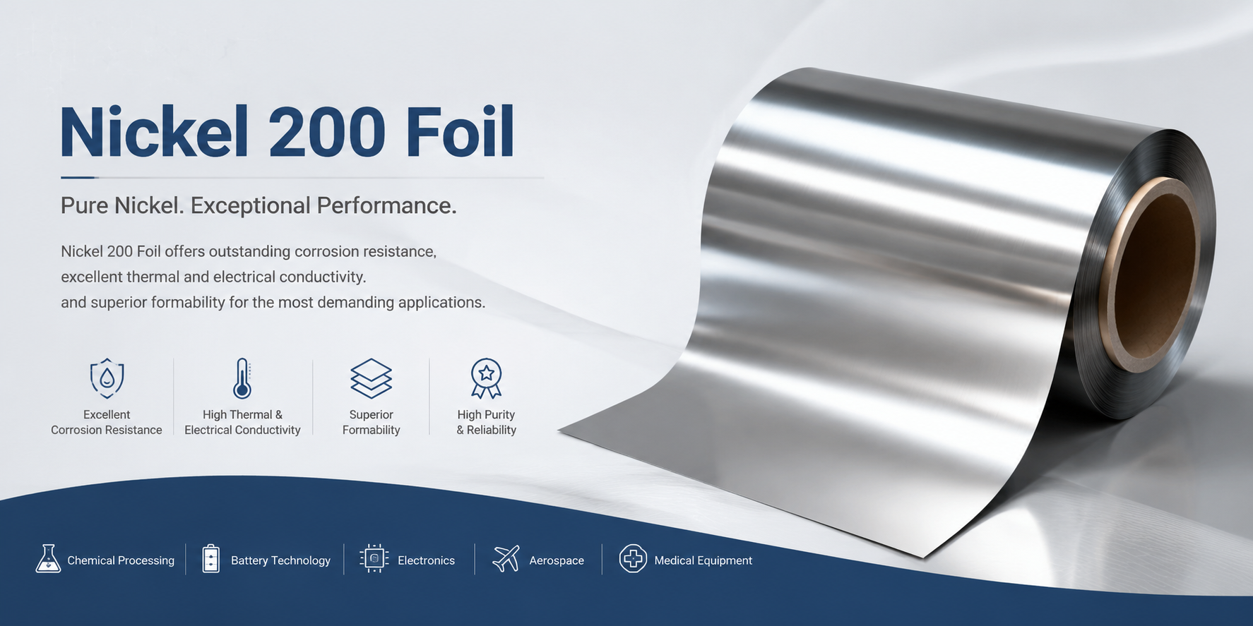
Nickel 200 foil, a high-purity commercial pure nickel material (Ni ≥ 99.6%), is widely used in modern industrial manufacturing where electrical conductivity directly determines the efficiency and reliability of electrical systems. Thanks to its excellent electrical conductivity, outstanding chemical stability, and superior formability, it plays a vital role in new energy batteries, electronics & electrical engineering, electrochemical industries, and other sectors. This ultra-thin metallic foil ensures continuous and stable current transmission while maintaining long-term performance stability in alkaline and reducing environments. This paper systematically analyzes the conductive characteristics of Nickel 200 foil, its influencing factors, practical application performance, and methods to optimize its electrical properties through precision manufacturing processes, providing engineers and procurement decision-makers with comprehensive insights into the technical value of this critical material.
1. Fundamental Conductive Characteristics of Nickel 200 Foil
1. Intrinsic Conductivity Advantages of Pure Nickel
The core competitive edge of Nickel 200 foil originates from its high nickel purity. When nickel content exceeds 99.6%, the internal lattice structure of the material becomes highly regular, significantly lowering resistance to free electron migration. Compared with structural materials such as titanium foil, pure nickel delivers several times higher electron transport capacity (the conductivity of pure nickel at room temperature is approximately 4 to 5 times that of commercially pure titanium). This advantage minimizes resistive losses and boosts overall system efficiency for applications including electrode connections, electromagnetic shielding, and battery tabs. The material features a density of 8.9 g/cm³ and high compactness, forming reliable conductive contact surfaces under appropriate assembly pressure.
2. Numerical Conductivity Performance and Test Conditions
The conductivity of industrial-grade Nickel 200 foil typically reaches 20%–25% of copper’s conductivity. Copper conductivity varies with purity: oxygen-free copper (≥99.95%) stands at roughly 58 MS/m, electrolytic copper (≥99.90%) at approximately 57 MS/m, and annealed Nickel 200 ranges from 11 to 12 MS/m (conversion formula: σ=1/ρ). While this value is lower than pure copper, Nickel 200 holds distinct advantages in service environments requiring robust corrosion resistance. Per ASTM B162, annealed Nickel 200 exhibits a typical resistivity of 9.5–10.5 μΩ·cm at 20 °C. For foil gauges ranging from 0.03 mm to 0.8 mm, conductivity maintains high consistency in practical testing, enabled by uniform microstructure homogenization achieved through precision rolling processes. Cold-worked foil contains abundant dislocations and lattice distortions that intensify electron scattering and slightly reduce conductivity; continuous annealing treatment restores conductivity to its optimal range effectively.
3. Temperature Dependence of Conductive Performance
Like all metallic conductors, Nickel 200 foil’s resistivity rises with increasing temperature. Within the room temperature to 200 °C range, its resistivity increases linearly at a rate of roughly 0.006 μΩ·cm/°C (data sourced from ASM Handbook, Volume 2: Properties and Selection: Nonferrous Alloys and Special-Purpose Materials, measured via four-point probe method inside a constant-temperature chamber with ±1 °C temperature precision). This characteristic is critical for designing heating elements and high-temperature electrical connections. Notably, Nickel 200 has a melting point of 1455 °C. It retains a stable single face-centered cubic (FCC) lattice with no phase transformations under operating temperatures of 300–500 °C, without significant performance degradation. Most organic conductive materials fully fail within this temperature window, highlighting the unique value of pure nickel foil for high-temperature electrical systems.
Table 1 Resistivity Variation of Nickel 200 Foil with Temperature (Baseline Temperature: 20 °C)
| Temperature Range | Resistivity Change¹ | Application Scenarios |
|---|---|---|
| 20–100 °C | Baseline Value +15% | Conventional Electronic Connections |
| 100–300 °C | Baseline Value +45% | Heating Elements |
| 300–500 °C | Baseline Value +80% | Vacuum Equipment |
2. Key Factors Affecting Nickel 200 Foil Conductivity
1. Material Purity and Trace Element Effects
Even trace impurity elements drastically degrade conductive performance. Chemical composition specifications for Nickel 200 foil enforce strict limits: C ≤ 0.02%, Fe ≤ 0.40%, Mn ≤ 0.35%, S ≤ 0.01%. Excess secondary-phase elements form non-conductive compounds (e.g., MnS, FeO) at grain boundaries that block electron transport pathways. Sulfur control (≤0.01%) is especially critical: excessive sulfur induces hot-working brittleness and indirectly disrupts microstructure uniformity. High-purity nickel feedstock produced via electrolytic nickel + vacuum double smelting minimizes harmful impurities, allowing finished foil conductivity to approach theoretical maximums. This is the fundamental reason for the notable conductivity gap between industrial pure nickel foil and standard nickel alloys.
2. Microstructure Regulation via Manufacturing Processes
Multi-pass precision cold rolling constitutes the core process for manufacturing ultra-thin Nickel 200 foil, yet excessive cold work introduces dense dislocations and strain that raise electron scattering frequency. Twenty-high rolling mills deliver thickness tolerance control of ±0.001 mm, ensuring uniform geometric dimensions and consistent work hardening across the full foil width. Intermediate annealing temperature control (±2 °C) directly governs recrystallization completeness: full stress-relief annealing eliminates cold-work dislocations and lattice distortions to remove electron scattering sources and restore intrinsic conductivity. Continuous annealing furnaces utilize argon shielding atmosphere with dew points below -40 °C to prevent surface oxidation and insulating oxide layer formation. Standard process parameters are listed as follows: heating zone temperature 700–750 °C, soaking zone temperature 650–700 °C, soaking duration 5–10 min, forced air cooling with wind speeds of 2–5 m/s. Closed-loop correlation control linking process parameters, microstructure and electrical performance enables stable mass production with high uniform conductivity.
3. Surface Condition and Contact Resistance Correlation
Interfacial contact resistance often accounts for a substantial portion of total resistance in conductive applications. After ultrasonic cleaning and alkaline treatment, Nickel 200 foil maintains a consistent dyne level of 44 mN/m (measured with dyne pens per ASTM D2578 at ±1 mN/m precision; this standard originally applies to polyolefin films and is widely adopted across the industry for this test). This surface characteristic delivers excellent wettability and formability. Clean surfaces form tight metallic joints during welding or crimping, minimizing contact resistance. Different surface finishing treatments (pickled, bright, matte) alter micro-roughness and oxide film thickness, thereby modifying contact performance. Bright-finish foil exhibits thinner oxide layers and lower welding resistance for battery tab welding applications. Uncontrolled edge burrs generated during slitting create current concentration zones that trigger localized overheating, potentially causing weld burn-through and accelerated regional oxidation in severe cases.
Table 2 Contact Resistance Comparison for Different Surface Finishes (20 °C, Four-Point Probe Test, n=5 Samples)
| Surface Finish | Contact Resistance (20 °C, Four-Point Probe, n=5) | Applicable Scenarios |
|---|---|---|
| Bright Annealed | Lowest | Precision Welding |
| Pickled | Moderate | General Electrical Connections |
| Matte | Slightly Elevated | Structural Components |
3. Conductive Performance of Nickel 200 Foil in Electrochemical Systems
1. Long-Term Current Transmission Stability in Alkaline Media
Electrode materials deployed in alkaline water electrolysis for hydrogen production and alkaline fuel cells require sustained current transfer under long-term immersion in strong alkaline solutions. Nickel 200 foil demonstrates exceptional corrosion resistance in sodium hydroxide (NaOH) and potassium hydroxide (KOH) media, forming only an ultra-thin passivation film that neither spalls nor thickens continuously. This passivation layer consists of low-valent nickel oxides with semiconducting properties that conduct electrons, unlike the highly resistive insulating titanium oxide film formed on titanium surfaces. Under standardized testing conditions (6 mol/L KOH solution, 85 °C, current density 1000 A/m², electrode area 1 cm²) with 1000 hours of continuous operation, the ohmic polarization of Nickel 200 electrodes rises by merely 5%–8% (measured via electrochemical impedance spectroscopy across 0.1 Hz–100 kHz with ±1% testing error), far superior to stainless steel counterparts (which typically see polarization increases exceeding 30%). This stability makes Nickel 200 foil a preferred cathode material for alkaline electrolytic cells.
2. Performance Shifts During Electrochemical Polarization
When Nickel 200 foil acts as an electrode for redox reactions, its surface undergoes dynamic electrochemical polarization. Under cathodic protection, the material surface resides in a reducing environment with extremely low corrosion rates and negligible conductive performance degradation. When deployed as an anode, engineers must evaluate the impact of oxygen evolution reactions on surface integrity. Pure nickel exhibits a high oxygen evolution overpotential in alkaline environments, which suppresses side reactions and reduces energy consumption. Controlling current density below 500 A/m² prevents destructive thickening of the passivation film. Unlike coated electrode substrates, monolithic Nickel 200 foil eliminates coating delamination risks for large electrolytic cells operating continuously at high current densities, ensuring uniform current distribution over extended service life. This characteristic directly impacts energy consumption and finished product quality.
3. Resistance Control During New Energy Battery Tab Welding
Battery tab connections for new energy storage systems represent high-current, low-resistance operating conditions. Nickel 200 foil with gauges of 0.03–0.10 mm is bonded to cell anodes and cathodes via laser welding or ultrasonic welding, with joint resistance required to remain in the milliohm range. While the material’s inherent low resistivity provides a foundational advantage, welding parameters (energy input, dwell time, compression force) exert a greater influence on final contact resistance. Pulsed laser welding demands higher energy input due to nickel’s elevated melting point, yet moderate thermal conductivity rapidly dissipates heat to limit excessive heat-affected zone expansion while delivering uniform thermal distribution suited for precision welding. Metallographic inspection of qualified welds reveals complete metallurgical bonding with continuous grain growth spanning the material interface, the microstructural mechanism enabling ultra-low joint resistance.
Table 3 Joint Resistance Comparison Across Welding Processes (Four-Point Probe Test, n=10 Samples, ±0.2 mΩ Error Margin)
| Welding Method | Joint Resistance (Four-Point Probe, n=10, ±0.2 mΩ Error) | Production Efficiency | Equipment Capital Cost |
|---|---|---|---|
| Laser Welding | < 1 mΩ | High | High |
| Ultrasonic Welding | 1 ~ 2 mΩ | Medium | Medium |
| Spot Welding | 2 ~ 5 mΩ | Low | Low |
4. Conductive Performance Optimization via Precision Manufacturing Processes
1. Uniform Thickness Control During Rolling
Thickness fluctuations across ultra-thin foil directly translate to uneven resistance distribution. Traditional 4-high or 6-high rolling mills struggle to eliminate edge thickening and center thinning (crown defects) for foil thinner than 0.05 mm. Premium twenty-high precision rolling mills feature multi-layer work and backup roll configurations to distribute rolling pressure evenly across a maximum width of 670 mm. A thickness tolerance of ±0.001 mm limits thickness variation to only 2% for 0.05 mm gauge foil, restricting corresponding resistance fluctuation within 2% (resistance varies inversely with cross-sectional area). This dimensional uniformity is critical for manufacturing large-area electrodes or parallel conductor assemblies, preventing localized overheating induced by current concentration in low-resistance zones.
2. Microstructure Homogenization Mechanism via Continuous Annealing
Batch annealing carries lower upfront costs yet generates uneven temperature fields that create grain size disparities of up to 30% across foil sections. Continuous annealing lines deliver precise zoned temperature control (heating, soaking, cooling segments), ensuring identical thermal exposure for every meter of foil. Soaking zone temperature accuracy of ±2 °C enables highly consistent recrystallization, yielding uniform microstructures with average grain sizes of 5–10 μm (process conditions: 750 °C annealing temperature, 8 min soaking duration, 5 °C/s cooling rate). Fine, homogeneous grains deliver excellent ductility, though grain boundaries induce minor electron scattering. The core value of this process lies in eliminating cold-work dislocations and heterogeneous microstructures, resulting in overall superior conductivity compared to unannealed foil (dislocations and grain boundaries exert distinct scattering effects on electrons). Argon shielding atmosphere maintained at dew points below -40 °C fully mitigates oxidation and hydrogen embrittlement risks. Annealed foil retains a bright metallic surface and may be deployed directly for standard conductive applications without supplementary cleaning; ultra-high-purity service environments still require surface washing.
3. Quantitative Management of Surface Cleanliness
Surface contaminants including oil residues, oxides and metallic debris form insulating layers at conductive interfaces. Industrial-grade ultrasonic cleaning systems utilize 40 kHz cavitation to remove micro-particles smaller than 5 μm. Alkaline washing saponifies residual grease, followed by hot water rinsing and high-pressure air drying to reduce surface carbon residue below 10 mg/m² (quantified via elemental analysis and surface extraction testing). This cleanliness standard meets semiconductor-grade requirements and prevents outgassing contamination during electron beam welding and vacuum coating processes. Online dyne level monitoring (industry-adapted ASTM D2578 methodology) guarantees consistent wettability across full foil coils, a critical parameter for subsequent plating, adhesive bonding and welding operations. Highly clean surfaces slow oxidation rates during storage and extend usable shelf life.
5. Conductive Performance Matching for Distinct Application Scenarios
1. Skin Effect Considerations for Electromagnetic Shielding
In high-frequency electromagnetic fields, current concentrates along conductor surfaces, a phenomenon known as the skin effect. Shielding effectiveness depends on the relationship between shield thickness and skin depth. At a frequency of 1 GHz, Nickel 200 foil exhibits a skin depth of approximately 2 μm; 0.03 mm thick foil provides a 15x skin depth safety margin. Theoretical shielding effectiveness calculated from skin depth formulas exceeds 100 dB, yet real-world engineering factors including seam leakage, lap joint impedance and grounding performance reduce measured values by 20–30 dB relative to theoretical predictions. While nickel foil delivers lower conductivity than copper foil, its weak magnetic properties (compared to ferromagnetic materials) reduce magnetic coupling interference for certain use cases. For composite shielding structures, Nickel 200 foil serves as an outer corrosion-resistant conductive layer paired with high-conductivity inner copper foil to balance shielding efficiency and environmental durability.
2. Power Density Design for Heating Elements
Resistive heating applications demand controllable resistance values and uniform heat distribution. Nickel 200 foil with gauges of 0.1–0.3 mm may be cut into custom geometries to achieve power densities ranging from several watts to tens of watts per square centimeter. The material’s positive temperature coefficient of resistance delivers inherent overcurrent limiting self-protection, simplifying temperature control circuits and improving equipment safety. Under vacuum or inert gas atmospheres, nickel foil operates stably at temperatures up to 800 °C without significant oxidation, making it an ideal candidate for silicone rubber heaters and laboratory tube furnaces. Compared with resistance wire heating elements, foil heaters feature larger heating surfaces, faster thermal response and even temperature distribution, with service lifespans exceeding 10,000 hours under vacuum/inert protection.
3. Contact Reliability for Precision Electrical Connectors
Spring connectors and FPC connectors in electronic equipment require conductive materials with robust elasticity and low stable contact resistance. Cold-worked (Y temper) Nickel 200 foil delivers tensile strength of 500–600 MPa, enabling precision stamping into complex spring geometries. Nickel surfaces resist forming insulating oxide films, sustaining consistent contact resistance after thousands of insertion-extraction cycles. Nickel connectors outperform gold-plated copper alloys in sulfidation and salt spray corrosive environments at lower material cost. Selective gold or palladium plating on contact zones further boosts localized performance, while non-contact base material remains uncoated to balance technical performance and economic efficiency. This design approach is widely adopted across automotive electronics and industrial control systems.
Conclusion
Driven by high-purity nickel composition delivering superior electrical conductivity, stable performance in alkaline and electrochemical environments, and homogeneous microstructure enabled via precision rolling and annealing processes, Nickel 200 foil functions as a core conductive material for modern electrical and electrochemical systems. Its performance advantages span a broad spectrum of industrial applications, from low-resistance welding for battery tabs and long-duration stable operation in electrolytic electrodes to high-frequency electromagnetic shielding and high-temperature heating elements. Fully understanding and controlling factors governing conductive performance—purity specifications, process optimization, and surface quality management—maximizes material utilization value, elevates end-product competitiveness and improves overall system reliability.
FAQ
Q1: Does the conductivity of Nickel 200 foil degrade over service time?
Conductivity remains essentially stable under standard operating temperatures and non-oxidizing environments. Prolonged exposure to temperatures exceeding 500 °C may induce grain coarsening, and repeated bending can generate fatigue microcracks that trigger minor performance degradation; appropriate engineering design safety margins render these effects negligible.
Q2: How to select optimal nickel foil thickness for conductive requirements?
Material selection requires comprehensive evaluation of target current density, allowable voltage drop and mechanical strength. Applications carrying high current prioritize foil thickness above 0.1 mm to reduce resistance; precision electronics utilize 0.03–0.05 mm foil to conserve space and cut costs. High-frequency applications governed by skin effect require foil thickness exceeding three times the calculated skin depth.
Q3: Can Nickel 200 foil directly replace copper foil for conductive connections?
Nickel foil represents the superior alternative for applications demanding high corrosion resistance or continuous operating temperatures above 200 °C. Copper maintains superior inherent conductive performance for general use. Industry designs frequently implement nickel-copper composite structures or nickel plating on copper substrates to combine the strengths of both materials, balancing technical performance and total cost.
Contact Us
Baoji Titanium Valley Titanium Nickel Zirconium Material Processing Co., Ltd. specializes in manufacturing and supplying Nickel 200 foil. Equipped with world-class 750 mm twenty-high precision rolling mills, our facility achieves an annual output of 3,000 tons of ultra-thin wide-width nickel foil with thickness tolerance controlled at ±0.001 mm. We provide complete material test certificates and third-party inspection reports. For high-purity nickel foil inquiries or technical support, please email sales@titaniumvalleys.com.
References
1.Li Wei, Zhang Qiang. Research on Conductive Performance and Fabrication Process of Pure Nickel Foil[J]. Rare Metal Materials and Engineering, 2020, 49(5): 1678-1683.
2.Wang Jianguo, Zhao Minghui. Electrical Conductivity of Metallic Materials and Its Applications in Electrochemistry[M]. Beijing: Chemical Industry Press, 2018: 156-172.
3.Chen Jun, Liu Yang. Nickel-Based Electrode Materials and Modification for Alkaline Water Electrolysis[J]. Electrochemistry, 2021, 27(3): 312-319.
4.Huang Wei, Zhou Li. Application Technical Analysis of Nickel Foil in Electronic Connectors[J]. Electronic Process Technology, 2019, 40(2): 89-93.