
How to Machine Gr5 Titanium Rod Efficiently?
- Gr5 Titanium rod
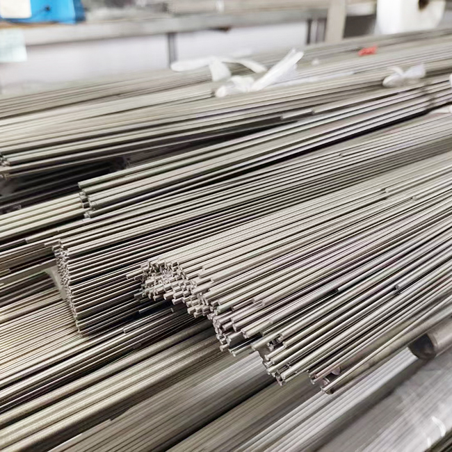
Gr5 titanium rod (Ti-6Al-4V) is the most widely used titanium alloy. It features excellent strength-to-weight ratio and corrosion resistance. It plays a key role in aerospace, medical devices and precision manufacturing. This material has unique machining characteristics. Its low thermal conductivity gathers heat at cutting zones. High chemical activity causes tool adhesion. Low elastic modulus leads to machining deflection. Different processes suit different tasks. Turning works well for roughing shaft parts. Milling forms complex profiles. Grinding delivers micron-level precision. Electrical discharge machining handles hardened layers.
1 How Material Properties Affect Machining of Gr5 Titanium Rod
Gr5 titanium alloy has thermal conductivity around 1/7 of steel, roughly 7.2 W/(m·K). Over 80% cutting heat concentrates at tool tips. The temperature reaches 800 ℃ to 1000 ℃ and accelerates tool wear or edge chipping. Titanium grows chemically active at high temperatures. It reacts with tool materials and forms adhesive layers. This changes tool geometry and ruins surface finish. Cemented carbide tools only last 1/10 of their service life when cutting steel. Its elastic modulus stands at about 110 GPa, much lower than 200 GPa for steel. The material bounces back after tool passage. Actual cutting depth falls below preset value. Thin-walled parts and slender shafts easily go out of tolerance and form surface waviness. We need targeted solutions. Use low speed and high feed plus high-pressure cooling to control temperature. Choose PCD or coated tools to reduce adhesion. Use sharp tools and enhance fixture rigidity to limit deflection.
2 Key Turning Parameters for Gr5 Titanium Rod
2.1 Tool Material and Geometry Selection
Cemented carbide of YG grade has good toughness and heat resistance. It fits rough turning. TiAlN or TiCN coated carbide greatly extends tool life for semi-finishing. PCD tools cost more but deliver superior surface finish and long service life for finishing. Set rake angle to 12° ~ 15° to lower cutting force. Set clearance angle to 8° ~ 12° to reduce friction. Set major cutting edge angle to 45° ~ 75° to improve heat dissipation. Perform edge honing at R0.02 mm ~ R0.05 mm to strengthen cutting edges.
2.2 Matching Turning Parameters
| Machining Stage | Cutting Speed (m/min) | Feed Rate (mm/r) | Cutting Depth (mm) | Recommended Tool Material |
|---|---|---|---|---|
| Rough Turning | 30 ~ 50 | 0.2 ~ 0.4 | 2 ~ 4 | YG Cemented Carbide |
| Semi-finishing Turning | 50 ~ 80 | 0.1 ~ 0.2 | 0.5 ~ 1.5 | TiAlN Coated Tool |
| Finishing Turning | 80 ~ 120 | 0.05 ~ 0.1 | 0.2 ~ 0.5 | PCD Tool |
Note. Excessively high cutting speed causes rapid tool wear. Too low speed reduces efficiency and builds up built-up edge. Coordinate feed rate and cutting depth. Increase values for roughing to raise efficiency. Reduce values for finishing to guarantee surface quality. Constant cutting force systems adjust parameters in real time based on monitoring data. They boost tool life by 30% to 50%.
2.3 Cooling and Lubrication Requirements
Use sufficient cutting fluid for turning Gr5 titanium rod. Water-soluble cutting fluid with 8% ~ 12% concentration or extreme-pressure emulsion works well. Set cooling pressure above 5 MPa. High-pressure coolant penetrates cutting zones and carries away chips. Keep fluid flow above 20 L/min. Point nozzles at the contact area between tool rake face and workpieces. Cool fluid down to 5 ℃ ~ 10 ℃ for precision machining to control thermal deflection. Never use chlorine-containing cutting fluid. It triggers stress corrosion cracking on titanium.
3 Key Points for Milling and Drilling Gr5 Titanium Rod
3.1 Milling Tool and Tool Path Design
Solid carbide end mills with 4 to 6 flutes suit groove and cavity milling. Set helix angle to 35° ~ 40° to lower cutting impact. Indexable face mills work for face milling. Set major cutting edge angle to 75° ~ 90°. Choose inserts with chip breakers. Use climb milling instead of conventional milling. Climb milling changes chip thickness from maximum to minimum and avoids work hardening. Conventional milling easily forms hardened layers. Adopt circular interpolation or trochoidal milling. Prevent sudden direction changes that bring impact load.
3.2 Adjustable Milling Parameters
| Milling Type | Cutting Speed (m/min) | Feed per Tooth (mm/z) | Radial Depth of Cut | Axial Depth of Cut (mm) |
|---|---|---|---|---|
| Face Milling | 40 ~ 70 | 0.05 ~ 0.15 | ≤ 70% of Tool Diameter | 1 ~ 3 |
| Side Milling | 30 ~ 60 | 0.03 ~ 0.10 | ≤ 30% of Tool Diameter | 2 ~ 5 |
| Cavity Milling | 50 ~ 90 | 0.08 ~ 0.20 | Subject to Tool Strength | 0.5 ~ 2 |
Note. Adjust milling parameters according to tool wear. Use upper limit values for new tools. Reduce speed and feed when tools wear out. Keep radial depth of cut below 50% of tool diameter. Control axial depth of cut properly to avoid tool breakage. Variable-frequency spindles with constant torque control adapt to changing cutting load.
3.3 Special Drilling Solutions
Drilling Gr5 titanium rod easily causes chip clogging, enlarged holes and rough bore surfaces. Set drill point angle to 130° ~ 140°, instead of the standard 118°. Grind chisel edges to reduce axial force. Keep drilling speed at 8 m/min ~ 15 m/min and feed rate at 0.05 mm/r ~ 0.15 mm/r. Use intermittent feed for holes with depth-to-diameter ratio over 5 mm. Retract drills after every 1 to 2 times of hole depth to remove chips. Equip tools with internal cooling. Adopt two-step machining: pilot hole first then reaming. Carbide drills outperform high-speed steel drills. Coated drills gain longer service life.
4 Advanced Precision Machining Technologies for Gr5 Titanium Rod
4.1 Grinding for Micron-level Precision
CBN grinding wheels are the top choice. Use 60 ~ 120 grit for rough grinding and 120 ~ 240 grit for finish grinding. Vitrified wheels resist high temperatures. Resin wheels deliver superior surface finish. Set wheel peripheral speed to 25 m/s ~ 35 m/s and workpiece speed to 30 m/min ~ 80 m/min. Keep feed rate at 0.005 mm/r ~ 0.02 mm/r. Set single-side grinding depth to 0.005 mm ~ 0.015 mm for rough grinding and 0.002 mm ~ 0.005 mm for finish grinding. Supply enough grinding fluid above 30 L/min to prevent grinding burn.
4.2 Electrical Discharge Machining (EDM) for Special Tasks
Use EDM for hardened Gr5 titanium, tiny deep holes and irregular holes. EDM creates no cutting force or machining deflection regardless of material hardness. Choose graphite or copper as electrodes. Use deionized water or kerosene as working fluid. Set current to 10 A ~ 30 A and pulse width to 100 μs ~ 500 μs for roughing. Set current to 1 A ~ 5 A and pulse width to 10 μs ~ 50 μs for finishing. EDM leaves a recast layer of 5 μm ~ 15 μm. Remove this layer via mechanical polishing afterwards. EDM runs slower but is irreplaceable for complex molds and medical parts.
4.3 Ultrasonic-assisted Machining
Apply ultrasonic vibration to tools or workpieces. Vibration frequency ranges from 15 kHz to 40 kHz and amplitude from 5 μm to 20 μm. Continuous cutting turns into intermittent impact. This method cuts cutting force by 30% to 50% and lowers cutting temperature by 20% to 30%. Tool life increases 2 to 3 times. Ultrasonic vibration breaks contact between chips and tools and improves chip removal. It works well for thin-walled titanium parts and micro structures. Match ultrasonic generator power with machining load. Excessive amplitude damages tools. Insufficient amplitude brings no obvious effect.
5 Build Quality Control System for Gr5 Titanium Rod Machining
5.1 Process Monitoring and Adaptive Adjustment
Modern CNC systems collect spindle power, cutting force, vibration and tool wear data in real time. Set threshold values for early warning. The system reduces feed rate or stops operation when cutting force rises by 15% or vibration exceeds limits. Adaptive algorithms optimize parameters based on material removal rate and surface roughness. A manufacturer applied this system for aerospace structural parts. Defect rate dropped from 8% to below 2%. Tool costs fell by 25%.
5.2 Surface Integrity Inspection
| Inspection Item | Test Method | Aerospace Standard | Medical Standard (ISO 1302) |
|---|---|---|---|
| Surface Roughness | Profilometer | Ra ≤ 1.6 μm | Ra ≤ 0.4 μm |
| Hardened Layer Depth | Metallographic Analysis | ≤ 50 μm | ≤ 30 μm |
| Residual Stress | X-ray Diffraction | Prefer Compressive Stress | Compressive Stress ≥ 150 MPa |
| Micro Crack | Fluorescent Penetrant Inspection | No Visible Crack | No Surface Defect |
Note. Surface integrity directly affects fatigue life and service reliability. Thick hardened layers easily form cracks. Tensile residual stress weakens fatigue performance. Optimize cutting parameters, tool geometry and cooling conditions. Keep hardened layer below 20 μm and turn residual stress into compressive stress. Perform 100% fluorescent penetrant inspection on aerospace parts. Use ultrasonic testing for medical implants to rule out internal defects.
5.3 Tool Management and Replacement Strategy
Tool costs account for 30% to 40% of total expenditure for titanium machining. Build tool life databases to record wear patterns under different working conditions. Use tool presetters for offline measurement and shorten on-machine setup time. Assign unique codes to every tool for full service tracking. Replace tools regularly based on cutting length or part quantity, instead of running tools to complete failure. Re-grind and re-coat used coated tools. Re-sharpen PCD tools multiple times. Bulk purchase and long-term cooperation with suppliers cut tool costs by 15% to 20%.
Conclusion
Machining Gr5 titanium rod requires systematic planning. Material characteristics, process selection, parameter optimization and quality control link closely. Use YG carbide and TiAlN coated tools with low speed and high feed for turning. Adopt climb milling and trochoidal paths to avoid work hardening. Use CBN wheels and sufficient fluid for micron-level grinding. Apply ultrasonic assistance to reduce cutting force. Technologies like PCD tools, high-pressure cooling and adaptive control raise precision and cut costs continuously. Master these core techniques to gain advantages in aerospace, medical and high-end manufacturing fields.
FAQ
1. What causes rapid tool wear during Gr5 titanium machining?
2. How to avoid deflection of thin-walled Gr5 titanium parts?
3. Why do chips clog and holes expand when drilling Gr5 titanium?
Partner with Titanium Valley for Gr5 Titanium Rod Solutions
Baoji Titanium Valley Titanium Nickel Zirconium Material Processing Co., Ltd. is a professional manufacturer and supplier of Gr5 titanium rod. We run Italian Danieli production lines. Our products comply with ASTM B348. We provide full-size Gr5 titanium rod from φ4 mm to φ300 mm and custom machining services. Send your technical requirements to sales@titaniumvalleys.com. Our team will deliver professional proposals and quotations within 48 hours.
References
- Zhao Yongqing, Qu Henglei. Machining Technology of Titanium Alloys [M]. Beijing: National Defense Industry Press, 2019.
- Chen Ming, Hou Yaohua, Zhang Weihong. Research Progress on Titanium Alloy Machining[J]. Aeronautical Manufacturing Technology, 2015(15): 26-31.
- Wang Xibin, Liu Lixian. High-efficiency Precision Machining for Difficult-to-cut Materials [M]. Beijing: China Machine Press, 2021.
- Liu Zhanqiang, Ai Xing. Overview of Titanium Alloy Machining Technology[J]. Tool Engineering, 2003, 37(1): 3-7.