
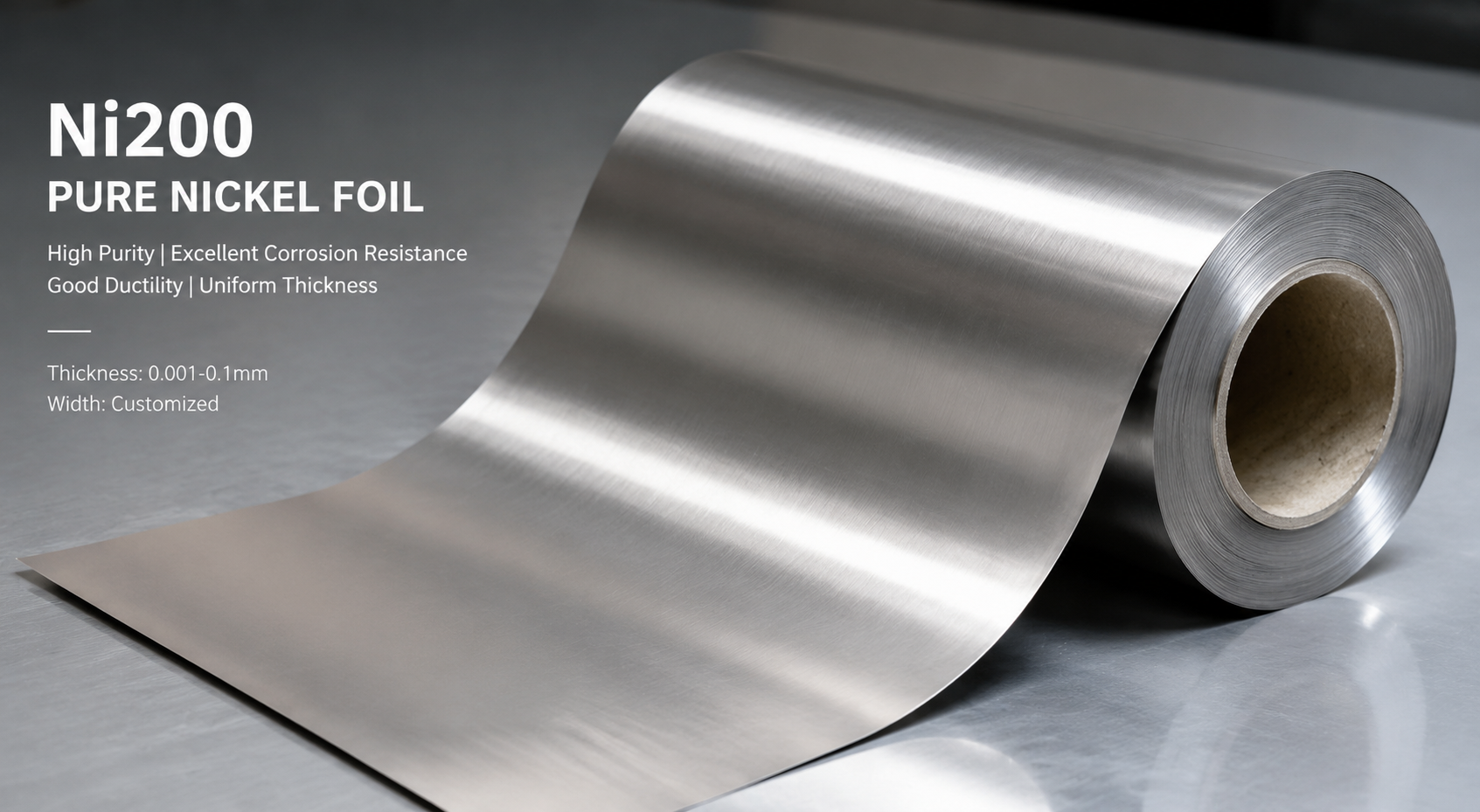
In heat exchanger manufacturing, material selection directly dictates equipment service life and operational efficiency. Ni200 pure nickel products (rods, tubes, plates, forgings) deliver outstanding corrosion resistance, superior thermal conductivity, and favorable formability, making them the preferred construction material for heat exchangers in chemical, energy, and marine engineering sectors. Manufacturing Ni200 heat exchangers requires rigorous control across the full workflow: material specification selection, machining processes, welding procedures, and quality assurance protocols. Proper implementation of standardized practices maximizes the material’s inherent performance advantages, extends equipment service life, reduces maintenance expenditures, and ensures uninterrupted production runs. This article systematically outlines critical application practices for Ni200 in heat exchanger production from a practical manufacturing perspective.
1. Why Ni200 Pure Nickel Is Required for Heat Exchanger Fabrication
1.1 Material-Related Challenges Faced by Industrial Heat Exchangers
Heat transfer equipment within modern chemical facilities operates continuously under harsh service conditions, including high-temperature alkaline solutions, chloride-containing fluids, and reducing environments, which impose severe demands on structural materials. For instance, 304 stainless steel readily undergoes caustic embrittlement (stress corrosion cracking) under residual tensile stress when exposed to sodium hydroxide solutions with concentrations ≥50% at temperatures ≥120 °C. Carbon steel exhibits drastically accelerated pitting corrosion rates in oxygen-bearing environments with chloride concentrations ≥5000 ppm. These failures lead to frequent fluid leakage, unplanned maintenance shutdowns, and compromised production continuity.
1.2 Core Performance Advantages of Ni200 Pure Nickel
Ni200 pure nickel features a minimum nickel content of 99.0%, a high-purity composition that delivers unique corrosion resistance properties. In reducing alkaline media free of oxidizing contaminants, Ni200 maintains stable corrosion resistance even at caustic concentrations up to 70% and operating temperatures exceeding 150 °C. Its room-temperature thermal conductivity reaches approximately 92 W/(m·K), enabling efficient heat transfer performance.
1.3 Practical Fabrication Advantages
Compared to high-nickel corrosion-resistant alloys, Ni200 exhibits lower overall hot and cold forming difficulty. Its weldability surpasses that of titanium alloys, eliminating the need for complex pre-weld and post-weld heat treatment procedures. The material boasts an elongation rate exceeding 40%, facilitating tube sheet machining, thread cutting, and production of complex-shaped components. Thin-walled assemblies fabricated from Ni200 generally require no mandatory preheating or post-weld heat treatment, significantly lowering production complexity and manufacturing costs.
2. Application of Ni200 in Critical Heat Exchanger Components
2.1 Material Selection and Machining of Tube Sheets and Baffles
| Component Type | Recommended Material Temper | Core Machining Processes | Performance Specifications |
|---|---|---|---|
| Tube Sheet | Annealed | Hot Forging + Precision Machining | Flatness ≤0.1 mm, Hole Diameter Tolerance ±0.05 mm |
| Baffle | Annealed | Stamping or Wire Electrical Discharge Machining | Surface Roughness Ra ≤6.3 for clean media Ra ≤3.2 for corrosive or fouling-prone media |
| Nozzle | Hot-Forged | Forging + Turning | Wall Thickness Uniformity ±5% |
| Flange | Annealed | Forging + Turning (Sealing Surface) | Sealing Surface Roughness Ra ≤3.2 |
3. Welding and Heat Treatment Procedures for Ni200 Heat Exchangers
3.1 Welding Consumable and Process Selection
For joining Ni200 to itself or other nickel-based alloys, ERNi-1 filler wire complying with AWS A5.14 is specified. Gas Tungsten Arc Welding (GTAW) is ideal for tube-to-tube sheet connections. For components with wall thicknesses ranging from 3 mm to 8 mm, welding current is set between 120 A and 160 A, with argon shielding gas flow rates of 10–15 L/min to ensure full backside shielding of weld joints. Pre-flow of high-purity argon (4N grade) prior to arc ignition and post-flow shielding after arc extinguishment are mandatory. Automated GTAW or submerged arc welding is suitable for mass production of shell longitudinal and circumferential seams.
Adequate gas shielding is critical: atmospheric exposure during welding generates oxide films that degrade joint corrosion resistance. Simultaneous front and backside shielding with ≥99.99% purity argon is required until weldments cool below 200 °C. For combined expansion-weld tube-to-tube sheet joints, the weld-first-then-expand sequence is preferred for high-temperature and high-pressure service conditions; the expand-first-then-weld sequence may be adopted for low-pressure equipment based on design specifications.
3.2 Post-Weld Treatment and Stress Relief
While mandatory post-weld heat treatment is not required for Ni200, stress-relief annealing is recommended for thick-walled components (wall thickness >20 mm) or welded assemblies subject to complex stress states. Weldments are heated to 600–650 °C, with hold time calculated as 1 hour per 25 mm of wall thickness. Furnace cooling to 300 °C is required prior to air cooling to eliminate the majority of residual stress and enhance resistance to stress corrosion cracking.
Hydrogen embrittlement represents a critical failure risk during Ni200 welding, particularly for thick-walled, highly restrained joints or welds performed in humid environments. Base metal and filler materials must be thoroughly dried and cleaned prior to welding; preheating the weld zone to 50–80 °C minimizes hydrogen absorption. A supplementary dehydrogenation hold at 250–300 °C for 2 hours is specified for equipment with stringent performance requirements.
3.3 Weld Inspection Acceptance Standards
All heat exchanger welds are classified as pressure boundary joints and subject to comprehensive non-destructive testing (NDT). Radiographic Testing (RT) or Ultrasonic Testing (UT) is utilized to detect internal discontinuities, complying with NB/T 47013 (domestic standard) and ASME Section V (international standard). Weld NDT quality grade shall meet or exceed Grade II. Surface examination via Liquid Penetrant Testing (PT) is performed; joints showing no crack or linear flaw indications are deemed acceptable.
Table 2 NDT Methods, Applicable Joint Locations, and Acceptance Criteria for Welds
| Inspection Method | Applicable Joint Locations | Acceptance Criteria | Supplementary Notes |
|---|---|---|---|
| Radiographic Testing (RT) | Full Penetration Butt Welds | Quality Grade ≥ Grade II (per NB/T 47013 or ASME Section V) | Primary method for thin and medium-thickness welds |
| Ultrasonic Testing (UT) | Butt Welds with Wall Thickness ≥12 mm | No discontinuity echoes exceeding allowable limits | RT is prioritized for welds with wall thickness <12 mm |
| Liquid Penetrant Testing (PT) | All Exterior Weld Surfaces | No cracks or linear flaw indications | Per ASME Section V or ISO 3452 |
| Gas Tightness Test | Fully Fabricated Welded Assembly | No visible fluid leakage; leak rates consistent with design documentation | Absolute zero leakage is not specified; allowable leak rates defined by design or contract requirements |
4. Core Quality Control Protocols for Heat Exchanger Manufacturing
4.1 Raw Material Receiving Inspection and Traceability Management
Upon Ni200 material delivery, material test certificates (MTCs) must be cross-referenced against physical stock. Rapid on-site chemical composition verification is completed via optical emission spectroscopy; laboratory chemical analysis is used for arbitration testing. Nickel content and impurity levels must satisfy ASTM B160 specifications. Mechanical property sampling includes tensile testing (minimum tensile strength ≥380 MPa, minimum elongation ≥40%) and hardness testing (maximum Brinell hardness HBW ≤90 for annealed temper).
A full batch traceability system is implemented with unique identification codes assigned to all raw materials and finished components. Identification markings are retained through all machining stages to enable rapid root-cause material sourcing in the event of non-conformities. This protocol is essential for pharmaceutical, food, and other industries with strict cleanliness requirements.
4.2 Dimensional Tolerance Control During Machining
Dimensional accuracy of mating components directly impacts sealing performance and heat transfer efficiency. Tube sheet hole diameter tolerance is maintained at ±0.05 mm; cumulative hole spacing error for sheets with overall length ≤2000 mm shall not exceed 0.3 mm, requiring CNC machining centers and custom tooling fixtures. Machining shop ambient temperature is stabilized at 20±2 °C to mitigate dimensional variation induced by thermal expansion and contraction.
Surface roughness strongly influences corrosion performance. All media-contacting surfaces receive precision finishing with roughness controlled between Ra 1.6 μm and Ra 3.2 μm. Smooth surfaces reduce media adhesion and fouling accumulation, lowering localized corrosion risk.
4.3 Finished Product Inspection and Performance Validation
Following fabrication, hydrostatic testing is performed to verify pressure boundary integrity. Test pressure is set to 1.5 times the design pressure (minimum water temperature of 5 °C), with a 30-minute hold period; assemblies showing no leakage or permanent deformation pass inspection. Equipment handling toxic or flammable media undergoes supplementary gas tightness testing using helium mass spectrometer leak detection, with a standard allowable leak rate of 1×10⁻⁶ to 1×10⁻⁷ Pa·m³/s for high-purity and toxic fluid service.
Heat transfer performance testing is conducted on dedicated test benches. Measured heat transfer coefficients and pressure drop values are compared against design calculations, with allowable deviation limited to ±10%. Standardized mass-produced models undergo sampling inspection per design and contract stipulations; custom-engineered heat exchangers require full 100% testing prior to shipment.
5. Industrial Application Practices and Case Studies
5.1 Mitigation of Severe Operating Conditions in Chlor-Alkali Industry
Chlor-alkali production circulates 30–50% sodium hydroxide solution at 100–130 °C, with trace chlorine and hypochlorite present. Conventional stainless steel heat exchangers exhibit a service life of only 1–2 years under standard operating conditions, while Ni200 heat exchangers deliver stable continuous operation for 8–10 years. Multiple chlor-alkali facilities report drastically reduced annual maintenance events and eliminated production downtime losses following Ni200 tube-and-shell heat exchanger installation.
Design specifications must prevent contact with high-temperature oxidizing media. When free chlorine or hypochlorite ions exist within process fluids, operating temperatures shall be limited to 80 °C or below, or composite Ni-titanium structures (nickel-titanium clad plate or segmented assembly) may be utilized to leverage complementary material performance. Periodic caustic cleaning removes fouling deposits to sustain heat transfer efficiency; Ni200 demonstrates inherent resistance to caustic cleaning solutions.
5.2 High-Purity Requirements for Electronic Electroplating Applications
Heating and cooling systems for electronic electroplating baths enforce strict material cleanliness standards. Dissolved metal ion contamination degrades plating quality and causes finished part rejection. Plate heat exchangers manufactured from Ni200 undergo electropolishing and ultrapure water passivation treatment, limiting surface metal ion leaching to ppb (μg/L) levels to meet semiconductor-grade purity standards.
Field data from multiple precision electronics and semiconductor manufacturers confirms reduced trace metal impurity concentrations within plating baths following Ni200 heat exchanger integration, with improved finished product yield. Disassembly inspection after five years of continuous operation reveals smooth, uncorroded heat transfer tube interiors, validating long-term material stability.
5.3 Chloride Corrosion Resistance for Marine Engineering
Multi-effect evaporators and heat recovery systems in seawater desalination operate continuously in high-salinity seawater (standard ambient seawater chloride concentration of 18,000–19,500 ppm) at elevated temperatures. Ni200 provides superior chloride corrosion resistance relative to standard stainless steel, yet pitting and under-deposit corrosion risks escalate above 60 °C. Ni200 is therefore designated for low-temperature heat exchanger sections (≤60 °C); titanium or duplex stainless steel is specified for high-temperature zones.
A seawater desalination project in the Middle East implemented a segmented Ni200/titanium hybrid design, reducing capital expenditure compared to full titanium construction while maintaining equivalent operational reliability. Three years of field operation confirmed Ni200 section corrosion rates below safety margins defined in design specifications.
Table 3 Operating Conditions and Technical Specifications for Ni200 Heat Exchangers Across Industrial Sectors
| Industrial Sector | Typical Operating Conditions | Ni200 Component Scope | Service Life | Key Technical Considerations |
|---|---|---|---|---|
| Chlor-Alkali | 30–50% NaOH, 100–130 °C | Tube Bundles, Tube Sheets | 8–10 Years | Avoid oxidizing media exposure; periodic caustic cleaning |
| Electronic Electroplating | Mixed electroplating baths, 40–80 °C | Plate Heat Exchangers | >10 Years | Electropolishing, ultrapure water passivation |
| Seawater Desalination | Seawater, 40–60 °C | Low-Temperature Heat Exchanger Sections | 5–8 Years | Strict temperature control; routine seawater flushing |
| Fine Chemical Processing | Oxidant-free organic solvents + alkaline media, 60–120 °C | Coils, Jackets | 6–8 Years | Rigorous weld quality control, post-weld stress relief |
Conclusion
Ni200 pure nickel delivers exceptional caustic corrosion resistance, excellent thermal conductivity, and favorable forming and welding characteristics, establishing it as a preferred construction material for heat exchangers within chemical, electronics, marine, and related industrial sectors. Proper material specification selection, standardized machining workflows, qualified welding procedures, and rigorous quality assurance form the foundation for unlocking Ni200’s full performance potential. Correct implementation of these practices extends equipment service life, lowers maintenance and operational expenditures, improves process stability, and generates substantial economic benefits for facility operators.
FAQ
Q1: Can Ni200 heat exchangers be utilized in oxidizing acid environments such as nitric acid?
Deployment is not recommended. Ni200 experiences drastically accelerated corrosion rates when exposed to oxidizing acids (nitric acid, chromic acid), oxidizing salts, or media containing free chlorine. Titanium alloys or Hastelloy grades are specified for these service environments. Limited low-temperature, weakly oxidizing applications may be evaluated via laboratory corrosion testing prior to conditional deployment.
Q2: What criteria determine when Ni200 heat exchangers require replacement?
Regular ultrasonic thickness gauging monitors wall thickness loss. Units require shutdown evaluation and potential replacement if remaining effective wall thickness falls below design corrosion allowance, wall thinning rates exceed allowable limits, fluid leakage occurs, heat transfer efficiency declines by more than 20%, or distinct pitting craters form on component surfaces.
Q3: Can Ni200 be directly welded to titanium alloy?
Direct fusion welding is prohibited. Significant disparities in physical and chemical properties produce brittle intermetallic compound formations at the joint interface. Connection methods including explosion-bonded clad plate, mechanical flanged joints, threaded couplings, or transition adapter fittings are specified instead.
Contact Us
Baoji Titanium Valley Titanium Nickel Zirconium Material Processing Co., Ltd. is a professional manufacturer and supplier of Ni200 pure nickel products, delivering end-to-end technical support covering material selection through project implementation. All products comply with international standards ASTM B160 and ASTM B564. Custom engineered solutions available upon request; email inquiries: sales@titaniumvalleys.com
References
1.Welding Branch of China Mechanical Engineering Society. Welding Handbook: Welding of Materials [M]. 3rd ed. Beijing: China Machine Press, 2016.
2.Chinese Society for Corrosion and Protection. Metal Corrosion Handbook [M]. 2nd ed. Beijing: Chemical Industry Press, 2019.
3.Chemical Equipment Design Center of Ministry of Chemical Industry. Chemical Equipment Design Handbook: Materials and Components [M]. Beijing: Chemical Industry Press, 2013.
4.ASTM B160-05(2019) Standard Specification for Nickel Rod and Bar.
5.ASTM B564-19 Standard Specification for Nickel Alloy Forgings.