
How Can You Extend the Service Life of GR2 Titanium Foil Components?
- Gr2 titanium foil
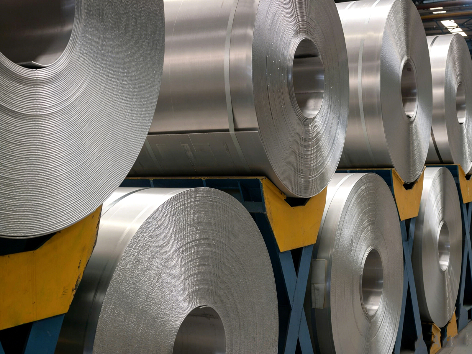
The service life of GR2 titanium foil components directly impacts equipment efficiency and maintenance costs. According to industrial practice data, a proper maintenance strategy can extend component lifespan by 40%-60%. Core maintenance techniques include: regular cleaning of surface contaminants to maintain passivation film integrity; controlling operating temperature to avoid prolonged service above 350 degrees Celsius; monitoring stress concentration areas to prevent fatigue crack propagation; adopting proper welding and joining processes to avoid heat-affected zone degradation; and establishing routine inspection mechanisms to detect early damage signals. These measures fully leverage GR2 titanium foil excellent corrosion resistance and ductility, significantly reducing unplanned downtime risk, particularly in harsh environments such as chemical processing, seawater desalination, and electrolysis equipment.
1. Surface Cleaning and Passivation Layer Maintenance Strategy
The superior corrosion resistance of GR2 titanium foil originates from the dense TiO2 passive film that spontaneously forms on its surface. This oxide layer, only a few nanometers thick, effectively isolates corrosive media. However, contaminant accumulation, mechanical damage, or chemical attack can compromise its integrity. Maintaining the passivation layer is the primary task for extending component service life.
(1) Contaminant Identification and Cleaning Interval Setup
Salt spray, grease, weld spatter, and chemical deposits in industrial environments form shielding layers on titanium foil surfaces, inhibiting oxygen contact and suppressing self-repair of the passive film. For seawater desalination equipment, alkaline cleaning is recommended quarterly; chemical reactors should be inspected monthly based on medium corrosivity. Avoid chlorine-containing cleaners; instead, use mild alkaline solutions with pH 8-11 combined with ultrasonic-assisted cleaning.
(2) Prevention and Repair of Mechanical Damage
Scratches during installation and transport disrupt passivation film continuity. Scratches deeper than 0.01mm require immediate treatment: gently polish with 2000-grit or finer sandpaper until smooth, then allow natural oxidation at room temperature for 48 hours or use a passivation solution such as nitric acid immersion at room temperature, with specific concentration and duration referencing applicable standards, to accelerate film reconstruction. Avoid hard tools such as wire brushes to prevent iron ion contamination.
(3) Chemical Environment Compatibility Assessment
Although GR2 titanium foil resists corrosion in most media, hydrofluoric acid at concentrations above 10 percent, hot concentrated sulfuric acid, and ferric chloride solutions can cause localized corrosion. Periodically inspect for pitting using dye penetrant testing; replace components when defects exceeding 0.5mm diameter are found. For hydrogen-embrittlement-sensitive applications such as electrolytic cell cathodes, conduct annual hydrogen content testing to ensure H remains at or below 150ppm within the safe threshold.
2. Temperature Control and Thermal Cycle Management
Temperature is a critical parameter affecting the mechanical properties and corrosion resistance of GR2 titanium foil. Although titanium has a melting point as high as 1668 degrees Celsius, industrial applications must strictly adhere to operating temperature limits to avoid performance degradation caused by microstructural evolution.
(1) Adherence to Long-Term Service Temperature Limits
ASTM B265 specifies that the maximum continuous service temperature for GR2 titanium foil shall not exceed 350 degrees Celsius. Exceeding this temperature leads to abnormal grain growth with grain size increasing from 30 micrometers to over 150 micrometers, reducing elongation by more than 15 percent and significantly increasing the risk of brittle fracture. Heat exchanger designs should include a 20-30 degrees Celsius safety margin, with temperature sensors for real-time monitoring and an alarm threshold set at 340 degrees Celsius.
(2) Thermal Shock Protection Measures
Titanium has a thermal conductivity of approximately 17 W per meter-Kelvin, similar to stainless steel at 16.3 W per meter-Kelvin, but its lower specific heat capacity means rapid temperature changes can still generate severe thermal stresses. During equipment startup and shutdown, heating and cooling rates should be controlled within 50 degrees Celsius per hour. For ultra-thin foils of 0.02 to 0.1mm, a staged preheating approach is recommended: room temperature to 150 degrees Celsius to operating temperature, holding 30 minutes at each stage to equalize the temperature field and prevent microcrack initiation from localized stress concentration.
(3) Heat Treatment Process Optimization
After cold working and forming, residual stresses in components can exceed 60 percent of the yield strength. Vacuum annealing at 650 to 750 degrees Celsius for 1 to 2 hours eliminates residual stresses and restores ductility. Key control points include: argon protection to prevent oxidation discoloration; cooling rate below 100 degrees Celsius per hour to prevent new stress formation; and post-annealing surface hardness reduced to HV 130 to 160. Each batch requires metallographic sampling to confirm uniform equiaxed grain distribution.
3. Stress Management and Fatigue Life Optimization
GR2 titanium foil components endure complex stress states under vibration, pressure pulses, and thermal cycling. Fatigue cracks are the primary failure mode in high-cycle service. Systematic stress management can improve fatigue life by 3 to 5 times.
(1) Eliminating Stress Concentration in the Design Phase
Part design should avoid sharp corners, sudden cross-section changes, and blind holes, features that concentrate stress. Fillet radius at hole edges should be at least 2 times the sheet thickness, with transition fillets of R at least 3mm. Finite element simulation shows that an R5 fillet reduces the stress concentration factor from 2.8 to 1.6 compared to R1, improving fatigue life approximately fourfold. For foils thinner than 0.5mm, use laser drilling instead of mechanical drilling to avoid residual tensile stresses from the plastic deformation layer around holes.
(2) Strain Monitoring During Service
Attach strain gauges to critical load-bearing areas for long-term monitoring, with a safety threshold of 0.002 corresponding to approximately 210 MPa stress, well below the yield strength. For high-stress zones such as chemical piping bends and heat exchanger U-tubes, perform ultrasonic thickness measurements annually; replace components when wall thinning exceeds 10 percent. Vibration equipment should use accelerometers; check for fastener loosening or crack propagation when resonant frequency drift exceeds 5 percent.
(3) Fatigue Crack Prevention in Welded Joints
Welded joints are the weakest points for fatigue. Proper welding procedure specifications must be followed: use GTAW or TIG welding with ERTi-2 filler wire, ensure 100 percent argon shielding on both sides, and control interpass temperature below 100 degrees Celsius. Post-weld grinding of weld toes to a smooth transition reduces stress concentration by 30 to 40 percent. Inspection standards are summarized in the table below.
Weld Defect Type | Inspection Method | Acceptance Criteria | Inspection Frequency |
Surface cracks | Fluorescent penetrant | No indication | 100 pct new equipment, annual during service |
Internal porosity | X-ray inspection | Individual pore <= 0.3mm, total area < 2 pct | 100 pct new equipment, recheck every 3 years |
Incomplete fusion or penetration | Ultrasonic testing | No defect signal | 100 pct new equipment, recheck every 2 years |
Grain coarsening | Metallographic examination | Grain size >= ASTM 6 | First piece of each batch, then spot-check every 3 years |
4. Welding Quality Assurance and Joint Protection
The reliability of welded joints determines the overall service life of GR2 titanium foil assemblies. Inadequate inert gas protection or improper welding parameters are the leading causes of joint degradation.
(1) Inert Gas Shielding Effectiveness Verification
During welding, the weld zone and heat-affected zone must be completely isolated from atmospheric oxygen and nitrogen. Back-side argon purity should exceed 99.995 percent, with positive pressure maintained at 0.02 to 0.05 MPa. A weld color that appears silvery-white or light straw indicates proper shielding; blue, purple, or gray coloring signifies oxygen and nitrogen pickup and requires rejection. For critical applications, use vacuum chambers or localized glove-box enclosures for welding.
(2) Weld Parameter Optimization and Process Control
Optimal welding parameters for GR2 titanium foil: current 80 to 150A, voltage 8 to 12V, travel speed 150 to 300mm per minute, wire feed rate matched to joint geometry. Preheating is generally not required for thicknesses below 1mm. Multi-pass welding requires interpass cleaning with stainless steel brushes dedicated to titanium only. Each pass must be visually inspected for discoloration before proceeding to the next.
(3) Post-Weld Heat Treatment and Surface Recovery
Post-weld annealing at 600 to 650 degrees Celsius for 30 to 60 minutes in argon atmosphere restores mechanical properties degraded by welding thermal cycles. Mechanical polishing or electropolishing removes discoloration and restores surface finish. For components in corrosive environments, a secondary passivation treatment with nitric acid immersion is recommended to rebuild the protective oxide layer.
5. Environmental Monitoring and Predictive Maintenance
Proactive environmental monitoring enables early detection of conditions that could accelerate GR2 titanium foil degradation, allowing timely intervention before catastrophic failure occurs.
(1) Corrosive Medium Concentration Tracking
Corrosion rates increase exponentially with temperature and aggressive ion concentration. For example, in 10 percent hydrochloric acid, raising temperature from 20 degrees Celsius to 60 degrees Celsius increases the corrosion rate 8 to 12 times. Install online pH meters, temperature sensors, and redox potential probes to establish a dynamic corrosion prediction model. When pH is below 2 and temperature exceeds 50 degrees Celsius, activate cooling systems or dilute the medium. Electrochemical impedance spectroscopy technology can monitor passivation film integrity in real time; a 50 percent drop in impedance value serves as a degradation warning signal.
(2) Mechanical Wear and Erosion Protection
High-velocity fluids or particle erosion cause surface thinning and accelerated corrosion from repeated passivation film destruction and repair. When flow velocity exceeds 5 meters per second, install flow deflectors to reduce local velocity or increase design thickness by 30 to 50 percent. Regularly measure thickness at critical locations and build thinning curves to predict remaining service life. For slurry transport pipelines, line with rubber or adopt titanium-rubber composite structures to reduce wear rates by over 70 percent.
(3) Special Assessment for Multi-Factor Coupling Conditions
Multi-factor failure modes such as stress corrosion cracking and hydrogen-induced cracking require specialized assessment. In high-pressure hydrogen environments such as methanol synthesis towers, conduct hydrogen permeation testing every two years to ensure hydrogen permeation rate remains below 0.01 mL per cm squared per hour. In high-temperature environments above 250 degrees Celsius with chloride ion concentration above 200ppm, perform slow strain rate testing annually to evaluate SCC susceptibility. Maintain a failure case database to identify weak points specific to your operational conditions.
Environmental Factor | Monitoring Parameter | Safety Threshold | Inspection Interval | Overlimit Response |
Chloride ion concentration | Ion chromatography | < 500ppm (room temp) < 200ppm (above 200C) | Monthly | Increase flush frequency or add inhibitor |
Dissolved oxygen | Online DO meter | < 8ppm (avoid pitting) | Continuous | Add deoxygenating agent or nitrogen seal |
pH fluctuation | Online pH meter | Range 2-12 | Continuous | Automatically add neutralizing agent |
Flow velocity | Ultrasonic flowmeter | < 5m/s (long-term) < 8m/s (short-term) | Weekly | Adjust valve or install buffer tank |
6. Conclusion
Life management of GR2 titanium foil components requires a systematic strategy: maintain passivation film integrity; strictly control operating temperature below 350 degrees Celsius; reduce stress concentration through design and monitoring; ensure welding quality and inert gas shielding; and establish real-time environmental parameter monitoring. Effective implementation of these measures can extend component service life beyond design values by 60 percent, reduce corrosion failure rates to below 5 percent, and is particularly suited for high-reliability applications in chemical processing, seawater desalination, and electrolysis equipment. The return on investment for periodic inspection and preventive maintenance typically exceeds 1:8.
FAQ
Q1: What is the typical service life of GR2 titanium foil components in seawater environments?
In seawater desalination systems, properly maintained GR2 titanium foil heat exchangers can serve for 15 to 20 years or more. Key factors include maintaining flow velocity below 3 meters per second, regularly removing biofouling layers, avoiding chloride ion concentration spikes above 1000ppm, and conducting annual ultrasonic thickness measurements to confirm uniform corrosion rates below 0.01mm per year.
Q2: How do you determine whether a titanium foil weld requires rework?
A three-step inspection method is used: visual examination of weld color (dark blue or gray is unacceptable); fluorescent penetrant testing for surface cracks (any linear indication requires rework); and radiographic inspection for internal porosity (individual pores above 0.3mm or dense distribution require rework). Rework must completely remove the defective area and re-weld; cumulative rework shall not exceed 2 times.
Q3: Does discoloration of GR2 titanium foil in chemical equipment affect performance?
Slight discoloration from silver-white to pale yellow typically indicates only thickening of the surface oxide film and does not affect corrosion resistance. However, dark blue or gray-black coloring indicates high-temperature oxidation or nitridation, leading to increased hardness and reduced toughness, requiring metallographic evaluation. Discoloration can be removed by pickling with HF and HNO3 at a 1:3 ratio solution immersion, but repeated discoloration indicates temperature control failure and requires inspection of the heating system.
Obtain Professional Maintenance Guidance
As a leading global manufacturer and supplier of GR2 Titanium Foil, Baoji Titanium Valley Titanium Nickel Zirconium Materials Processing Co., Ltd. (Titanium Valley) operates a production line with annual capacity of 3,000 metric tons of ultra-thin wide titanium foil, offering customized products with thicknesses from 0.02 to 1.0mm and widths from 15 to 680mm, along with full lifecycle technical support. Contact us for our component maintenance white paper and on-site assessment services: sales@titaniumvalleys.com
For a broader view of available grades, supply forms, and related specifications, explore our Titanium Foil category.
For product-level details and supply options, you can also review our ASTM F136 Gr5 Eli (Gr23) Titanium Foil page.
References
Li Xiaogang, Dong Chaofang. Corrosion Behavior and Protection Technology of Industrial Pure Titanium. Chemical Industry Press, 2019.
National Standard of China. Titanium and Titanium Alloy Sheets (GB/T 3621-2007). Standards Press of China, 2007.
Liu Jianrong, Zeng Liying. Research on Factors Affecting Fatigue Performance of Titanium and Titanium Alloy Welded Joints. Journal of the China Welding Institution, 2021, Vol. 42 No. 6, pp. 78-85.
Chen Zhenhua, et al. Fatigue and Fracture of Titanium Alloys. Science Press, 2018.